Quick Setup Guide
To make an EoIP tunnel between 2 routers which have IP addresses 10.5.8.1 and 10.1.0.1:
1.
On router with IP address 10.5.8.1, add an EoIP interface and set its MAC address:
/interface eoip add remote-address=10.1.0.1 tunnel-id=1 mac-address=00-00-5E-80-00-01 \
\... disabled=no
2.
On router with IP address 10.1.0.1, add an EoIP interface and set its MAC address::
/interface eoip add remote-address=10.5.8.1 tunnel-id=1 mac-address=00-00-5E-80-00-02 \
\... disabled=no
Now you can add IP addresses to the created EoIP interfaces from the same subnet.
EoIP Application Example
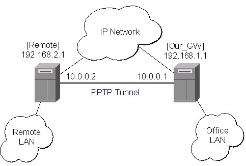
To make a secure Ethernet bridge between two routers you should:
1.
Create a PPTP tunnel between them. Our_GW will be the pptp server:
[admin@Our_GW] interface pptp-server> /ppp secret add name=joe service=pptp \
\... password=top_s3 local-address=10.0.0.1 remote-address=10.0.0.2
[admin@Our_GW] interface pptp-server> add name=from_remote user=joe
[admin@Our_GW] interface pptp-server> server set enable=yes
[admin@Our_GW] interface pptp-server> print
Flags: X - disabled, D - dynamic, R - running
# NAME USER MTU CLIENT-AD... UPTIME ENCODING
0 from_remote joe
[admin@Our_GW] interface pptp-server>
The Remote router will be the pptp client:
[admin@Remote] interface pptp-client> add name=pptp user=joe \
\... connect-to=192.168.1.1 password=top_s3 mtu=1500 mru=1500
[admin@Remote] interface pptp-client> enable pptp
[admin@Remote] interface pptp-client> print
Flags: X - disabled, R - running
0 R name="pptp" mtu=1500 mru=1500 connect-to=192.168.1.1 user="joe"
password="top_s2" profile=default add-default-route=no
[admin@Remote] interface pptp-client> monitor pptp
status: "connected"
uptime: 39m46s
encoding: "none"
[admin@Remote] interface pptp-client>
See the PPTP Interface Manual for more details on setting up encrypted channels.
2.
Configure the EoIP tunnel by adding the eoip tunnel interfaces at both routers. Use the ip addresses of the pptp tunnel interfaces when specifying the argument values for the EoIP tunnel:
[admin@Our_GW] interface eoip> add name="eoip-remote" tunnel-id=0 \
\... remote-address=10.0.0.2
[admin@Our_GW] interface eoip> enable eoip-remote
[admin@Our_GW] interface eoip> print
Flags: X - disabled, R - running
0 name=eoip-remote mtu=1500 arp=enabled remote-address=10.0.0.2 tunnel-id=0
[admin@Our_GW] interface eoip>
[admin@Remote] interface eoip> add name="eoip" tunnel-id=0 \
\... remote-address=10.0.0.1
[admin@Remote] interface eoip> enable eoip-main
[admin@Remote] interface eoip> print
Flags: X - disabled, R - running
0 name=eoip mtu=1500 arp=enabled remote-address=10.0.0.1 tunnel-id=0
[Remote] interface eoip>
3.
Enable bridging between the EoIP and Ethernet interfaces on both routers.
On the Our_GW:
[admin@Our_GW] interface bridge> add
[admin@Our_GW] interface bridge> print
Flags: X - disabled, R - running
0 R name="bridge1" mtu=1500 arp=enabled mac-address=00:00:00:00:00:00
protocol-mode=none priority=0x8000 auto-mac=yes
admin-mac=00:00:00:00:00:00 max-message-age=20s forward-delay=15s
transmit-hold-count=6 ageing-time=5m
[admin@Our_GW] interface bridge> port add bridge=bridge1 interface=eoip-remote
[admin@Our_GW] interface bridge> port add bridge=bridge1 interface=office-eth
[admin@Our_GW] interface bridge> port print
Flags: X - disabled, I - inactive, D - dynamic
# INTERFACE BRIDGE PRIORITY PATH-COST
0 eoip-remote bridge1 128 10
1 office-eth bridge1 128 10
[admin@Our_GW] interface bridge>
And the same for the Remote:
[admin@Remote] interface bridge> add
[admin@Remote] interface bridge> print
Flags: X - disabled, R - running
0 R name="bridge1" mtu=1500 arp=enabled mac-address=00:00:00:00:00:00
protocol-mode=none priority=0x8000 auto-mac=yes
admin-mac=00:00:00:00:00:00 max-message-age=20s forward-delay=15s
transmit-hold-count=6 ageing-time=5m
[admin@Remote] interface bridge> port add bridge=bridge1 interface=ether
[admin@Remote] interface bridge> port add bridge=bridge1 interface=eoip-main
[admin@Remote] interface bridge> port print
Flags: X - disabled, I - inactive, D - dynamic
# INTERFACE BRIDGE PRIORITY PATH-COST
0 ether bridge1 128 10
1 eoip-main bridge1 128 10
[admin@Remote] interface bridge>
4. Addresses from the same network can be used both in the Office LAN and in the Remote LAN.
source: http://www.mikrotik.com/testdocs/ros/3.0/vpn/eoip.php
Sabtu, 08 Maret 2008
EoIP

Minggu, 10 Februari 2008
Layer2 VPN Server
Ethernet over IP (EoIP) Tunneling is a MikroTik RouterOS protocol that creates an Ethernet tunnel between two routers on top of an IP connection. A VLAN is a logical grouping that allows end users to communicate as if they were physically connected to a single isolated LAN, independent of the physical configuration of the network.
It's required that you have switch that support 802.1Q VLAN and shows how to setup Layer 2 VPN Server. Configuration of switches not added coz it depends on how network you have.
With this example we group devices on one or more LANs that are configured ,so that they can communicate as if they were attached to the same wire when in fact they are located on a number of different LAN segments. Using EoIP you can reach routers that are connected by wireless and with vlans we then segment network. Because VLANs are based on logical instead of physical connections, they are extremely flexible. So, in my network i added a few location that goes througt fiber optic and about 40 wireless locations.
Server Side:
First, install latest Mikrotik OS on computer with 2 ethernet intefaces.
   Now lets configure them.

  /interface  set 0 name=ether1-internet
    set 1 name=ether2-trunk

  /ip address  add address=195.101.10.5/29 interface=ether1-internet comment="" disabled=no


 Create Eoip interface for remote router1:

 /interface eoip
  add name=eoip-router1 tunnel-id=310 remote-address=196.200.50.5 comment="" disabled=no

 Create vlan for remote router1:

  /interface vlan
  add name=vlan-router1 interface=ether2-trunk vlan-id=310 comment="" disabled=no
  Now bridge eoip and vlan:

  /interface bridge
  add name=bridge-to-router1

 /interface bridge port
  add interface=eoip-router1 bridge=bridge-to-router1
  add interface=vlan-router1 bridge=bridge-to-router1
Now we add configuration for remote router2
  Create Eoip interface for remote router2:

 /interface eoip
  add name="eoip-router2" tunnel-id=312 remote-address=196.200.50.6 comment="" disabled=no

 Create vlan for remote router2:

  /interface vlan
  add name=vlan-router2 interface=ether2-trunk vlan-id=312 comment="" disabled=no
  Now bridge eoip and vlan:

  /interface bridge
  add name=bridge-to-router2

 /interface bridge port
  add interface=eoip-router2 bridge=bridge-to-router2 comment="" disabled=no
  add interface=vlan-router2 bridge=bridge-to-router2 comment="" disabled=no
Remote Router1 side:
  /interface eoip
  add name=eoip-client remote-address=195.101.10.5 tunnel-id=310 comment="" disabled=no

 /interface bridge
  add name=bridge-to-router1

 /interface bridge port
  add interface=eoip-client bridge=bridge-to-router1 comment="" disabled=no
  add interface=ether1 bridge=bridge-to-router1 comment="" disabled=no
Remote Router2 side:
   /interface eoip
  add name=eoip-client remote-address=195.101.10.5 tunnel-id=312 comment="" disabled=no

 /interface bridge
  add name=bridge-to-router2

 /interface bridge port
  add interface=eoip-client bridge=bridge-to-router2 comment="" disabled=no
  add interface=ether1 bridge=bridge-to-router2 comment="" disabled=no
Depends on the network you have , some modifications are required , and dont forget to add and configure conresponding VLANS on Allied Telesyn, Cisco , etc. switches.
TIP: You can always add some address to bridge, just to check if there is connectivity to remote router with ping command.
Server side: /ip address
add adress=192.168.100.1/30 interface=bridge-to-router1 comment="" disabled=no
Remote router side: /ip address
 add address=192.168.100.2/30 interface=bridge-to-router1 comment="" disabled=no

from: http://wiki.mikrotik.com/wiki/Layer2_VPN_Server
Jumat, 08 Februari 2008
IPSec VPN with Dynamic Routing / Mikrotik and Cisco
Mikrotik RouterOS
If you are using ROS v3.0 or above, be sure to check the end of this list to see a list of necessary mod.
First should configure a Tunnel Interface:
   / interface ipip
  add name="Tunnel1" mtu=1480 local-address=10.10.1.100 remote-address=10.10.1.200 comment="" disabled=no
After that all interfaces are configured, than should asign IP addresses for interfaces:
   / ip address
  add address=10.10.1.100/24 network=10.10.1.0 broadcast=10.10.1.255 interface=WAN comment="" disabled=no
  add address=192.168.1.1/24 network=192.168.1.0 broadcast=192.168.1.255 interface=LAN comment="" disabled=no
  add address=172.16.0.1/30 network=172.16.0.0 broadcast=192.168.0.3 interface=Tunnel1 comment="" disabled=no
Enable Routing in Mikrotik Router, in this case RIP:
  / routing rip
 set redistribute-static=no redistribute-connected=no redistribute-ospf=no redistribute-bgp=no metric-static=1 \
 metric-connected=1  metric-ospf=1 metric-bgp=1 update-timer=30s timeout-timer=3m garbage-timer=2m
 / routing rip interface
 add interface=Tunnel1 receive=v2 send=v2 authentication=none authentication-key="" prefix-list-in="" prefix-list-out=""
 / routing rip neighbor
 add address=172.16.0.2
 / routing rip network
 add address=192.168.1.0/24
 add address=172.16.0.0/30
IPSec setup, here should be defined the ipsec policy, peer and proposal. Make sure that policy should not have enabled option tunnel, in this case tunel should be set to NO, because it will be used the transport mode of IPSec not the tunnel mode:
  / ip ipsec proposal
 add name="IPSec" auth-algorithms=md5 enc-algorithms=3des lifetime=30m lifebytes=0 pfs-group=modp1024 disabled=no
 / ip ipsec peer
 add address=10.10.1.200 secret="ipsec" generate-policy=no exchange-mode=main send-initial-contact=yes \
 proposal-check=obey   hash-algorithm=md5 enc-algorithm=3des dh-group=modp1024 lifetime=1d lifebytes=0 disabled=no
 / ip ipsec policy
 add src-address=10.10.1.100/32:any dst-address=10.10.1.200/32:any protocol=all action=encrypt level=require \
 ipsec-protocols=esp  tunnel=no sa-src-address=10.10.1.100 sa-dst-address=10.10.1.200 \
 proposal=IPSec manual-sa=none dont-fragment=clear disabled=no
In V3.0 the bolded line will change on:
  / routing rip interface
 add interface=Tunnel1 receive=v2 send=v2 authentication=none authentication-key="" in-prefix-list="" out-prefix-list=""
 / ip ipsec proposal
 add name="IPSec" auth-algorithms=md5 enc-algorithms=3des lifetime=30m pfs-group=modp1024 disabled=no
 / ip ipsec peer
 add address=10.10.1.200/32:500 secret="ipsec" generate-policy=no exchange-mode=main send-initial-contact=yes \
 proposal-check=obey   hash-algorithm=md5 enc-algorithm=3des dh-group=modp1024 lifetime=1d lifebytes=0 disabled=no
Cisco IOS
Cisco Interfaces and addresses:
  FastEthernet 0/0
  description *** WAN ***
  ip address 10.10.1.200 255.255.255.0
  crypto map vpn
  FastEthernet 0/1
  description *** LAN ***
  ip address 192.168.2.1 255.255.255.0
Cisco Tunnel Interface:
  interface Tunnel1
 description **Cisco Peer**
 ip address 172.16.0.2 255.255.255.252
 no ip redirects
 no ip unreachables
 no ip proxy-arp
 ip mtu 1480
 ip rip v2-broadcast
 ip tcp adjust-mss 1400
 load-interval 30
 tunnel source 10.10.1.200
 tunnel destination 10.10.1.100
 tunnel mode ipip
 hold-queue 1024 in
 hold-queue 1024 out
Routing in Cisco:
  router rip
  version 2
  timers basic 30 60 90 90
  redistribute connected metric 1 route-map connected-to-rip
  redistribute static metric 5 route-map static-to-rip
  network 172.16.0.2
  network 192.168.2.0
  distribute-list prefix LAN out
  no auto-summary
Setup the prefix-list to match the Local subnet:
ip prefix-list LAN seq 10 permit 192.168.2.0/24
Setup route-maps to match interfaces to be advertised by RIP:
  route-map connected-to-rip permit 10
 match interface FastEthernet0/0
 !
 route-map static-to-rip permit 10
 match ip address prefix-list LAN
IPSec and Crypto setup in Cisco, also here trasnport mode of IPSec should be setup:
 !
 crypto isakmp policy 1
  encr 3des
  hash md5
  authentication pre-share
  group 2
 !
 crypto isakmp key ipsec address 0.0.0.0 0.0.0.0
 !
 crypto ipsec security-association idle-time 600
 !
 crypto ipsec transform-set vpn esp-3des esp-md5-hmac
  mode transport
 !
 crypto map vpn 1 ipsec-isakmp
  description **To Mikrotik Peer**
  set peer 10.10.1.100
  set transform-set vpn
  set pfs group2
  match address mikrotik_peer
 !
Setup access-list to match the IPSec peer:
  ip access-list extended mikrotik_peer
  permit ipinip host 10.10.1.200 host 10.10.1.100
Type this in "enable" mode to view your routing table (after succesfull RIP update):
sh ip route
or
sh ip rip database
This example can be implemented also with another routing protocol like OSPF, and also very simply we can setup here a failover connection. Regarding the failover, the setup is very easy, all that we need is to create another set of tunnels via another ISP or gateway, but again the remote peer is the same router. Instead of the routing protocol for the second set of tunnels, it needs static routes to be configured, only that the static routes should have higher distance than the dynamic protocol. The idea is that, when the primary link will go down (dynamic routing distance=120) than the backup link becomes active (static routes distance=200), as soon as the primary link will come up, it will put the failover link in inactive mode.Titolo del collegamento
from http://wiki.mikrotik.com/wiki/IPSec_VPN_with_Dynamic_Routing_/_Mikrotik_and_Cisco